Cloud TAP - Setting up a traffic output
Goal: In this article, we will go through the process of setting up a simple output of traffic mirrored from Kubernetes application pods to a destination, using the Supervisor Cloud TAP module.
Requirements: Profitap Supervisor with an active Cloud TAP module license, Kubernetes cluster with one or more application pods.
Scenario: First, we will register the Kubernetes cluster on Supervisor. Then, we will define a group of application pods to target, and create a tunnel destination. Finally, we will link the pod group and the tunnel destination by creating and deploying a traffic rule.
Note: The “destination” mentioned in this article refers to an assumed destination where the mirrored traffic should be sent to, e.g. for analysis purposes.

Registering a Kubernetes cluster
Open the Supervisor interface and navigate to the Cloud TAP section via the main menu.

If you wish to register the cluster on a separate virtual network from the existing ones, click the Add Network button to create a new network. Enter a name for the new virtual network, and click the Confirm button.

Click the Add Virtual Environment button to register a cluster. Set Type to Kubernetes, enter the cluster information, select a virtual network to assign it to, then click the Confirm button.
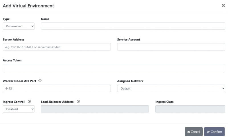
- Type: The type of environment [Azure/Kubernetes].
- Name: A name for the virtual environment.
- Server Address: The IP address or server name of the kubernetes API server. The L4 port can be specified if required by the server configuration.
- Service Account: The service account under which the token was created. This service account must be within the
profitapnamespace. - Access Token: This token will be used to access the kubernetes master node. Please refer to the following article for creating the token: Creating token for Supervisor access.
- Worker Nodes API Port: The port number on the worker node(s) that the tapping pod will listen on. Supervisor will communicate with the tapping pod through this port, so it should be made accessible and not blocked.
- Assigned Network: The virtual network that the virtual environment will be assigned to.
- Ingress Control: In case an ingress controller is deployed on the kubernetes cluster.
- Disabled: No ingress controller.
- Default: Default ingress class configured on the cluster.
- Custom: Specific ingress class associated with the chosen ingress controller.
- Load-Balancer Address: The IP address or server name of the load balancer service. The L4 port can be specified if necessary.
- Ingress Class: Name of the ingress class (e.g. nginx).
The default ingress class can be viewed using the following command (if configured):
kubectl get ingressclass -o=jsonpath='{range .items[*]}{.metadata.name}{"\t"}{.metadata.annotations.ingressclass\.kubernetes\.io/is-default-class}{"\n"}{end}'
The new environment will appear in the list of registered clusters, and its state will display CONNECTED if Supervisor is able to communicate with it.

Defining a group of application pods
Click the newly registered cluster to open its details window.

On this window, click either the Create Static Pod Group or Create Dynamic Pod Group button to begin creating a pod group:
- Static Pod Groups contain specific pods that are manually selected. Set a name for the group, select which traffic direction to monitor (ingress, egress, or both), and select the pods to include in the group.
- Dynamic Pod Groups contain any pods matching a name filter, and are automatically updated to include new pods whose names match that filter. Set a name for the group, select which traffic direction to monitor (ingress, egress, or both), and set a Match Filter to match the name of the pods to automatically include in the group.
In this example, we will create a dynamic pod group called “nginx-service”, with matching filter “nginx”, to include any present and future pod with “nginx” in its name. Click the Confirm button to complete the creation of the pod group.


Creating a tunnel destination
Again on the cluster details window, click the Create Destination button to begin creating a new tunnel destination. This is where the mirrored traffic from the application pods should be sent to, encapsulated in a GRE-TAP tunnel. Set a name, enter the IPv4 address of the destination, and enter the GRE-TAP tunnel ID. Set the MTU options as desired. Click the Confirm button to complete the creation of the tunnel destination.


Creating and deploying a traffic rule
Navigate to the Traffic Management section via the main menu.

Select the appropriate network in the Selected Network drop-down menu at the top of the page. Click the Initialize Network button, select the Kubernetes cluster, and click Confirm.

The cluster, pod group and tunnel destination should appear in the graphical view.

Open the Rule Sets tab at the top of the page.

Click the Create Rule Set button to begin creating a new rule set. Enter a name and optionally a description for the rule set, ensure the selected Virtual Network is correct, and click Confirm.

The rule set should now appear in the list.

Click the Configure Rule Set ![]() button to open the rule set. Rules, L4 port groups and VLAN ID groups can be created in this view. L4 port groups and VLAN ID groups are used for filtering in the traffic rules. In this case, we will create a simple rule.
button to open the rule set. Rules, L4 port groups and VLAN ID groups can be created in this view. L4 port groups and VLAN ID groups are used for filtering in the traffic rules. In this case, we will create a simple rule.

Click the Create Rule button to open the rule creation window. Enter a name for the rule, and select the traffic sources. In this case, we will select the pod group we have created earlier. Click the Add button, then the Add Pod Group option.

In the new drop-down menu that appears, select the pod group, then click the Apply Port Group Source ![]() button.
button.


Click the Next button at the bottom of the window or the Traffic Destinations step at the top of the window. Click the Add button, then the Add Tunnel Destination option.

In the new drop-down menu that appears, select the tunnel destination, then click the Apply Port Group Destination ![]() button.
button.


Click the Next button at the bottom of the window or the Filters step at the top of the window. Traffic filters can be defined in this view, and are described in the Traffic management article. In this case, will create a rule without filtering.

Click the Next button at the bottom of the window or the Advanced step at the top of the window. Advanced options can be defined in this view if available. In this case, no advanced options are available.

Click the Next button at the bottom of the window or the Rule Overview step at the top of the window. Verify that the information is correct, then click the Confirm button.

With the rule now created, we can deploy the rule set by clicking the Apply Current Rule Set button at the top of the page.
