Troubleshooting failed connection attempts
Learn more about the IOTA solution at profitap.com/iota
Problem description
Network analysts and security specialists often have to analyze why certain communication relationships cannot be established. Security solutions such as firewalls, Intrusion Prevention Systems, or TLS inspection appliances often cause failed attempts to establish a connection.
Getting started
The following example provides an overview of how an analysis of faulty connection setups with the Profitap IOTA can take place based on a step-by-step guide. After preparing the capture and analysis appliance, we show how you can determine the root cause of faulty connection attempts in the first part.
In this example, we are talking about an attempt to establish a connection to a web server on the public Internet.
As the first step, we need to configure the physical interface. To do this, we navigate to the “Capture” menu in the left menu tree and then to the “Interface Configuration” section. The interface is configured as SPAN (out-of-band) with 10/100/1000 Mbit/s Auto-Negotiation as shown below, meaning both physical interfaces can receive the traffic to be analyzed from a SPAN port or a TAP. If the IOTA is to be integrated in-line into the data stream, the checkbox next to “Inline Mode” must be ticked and the “Save” button clicked.
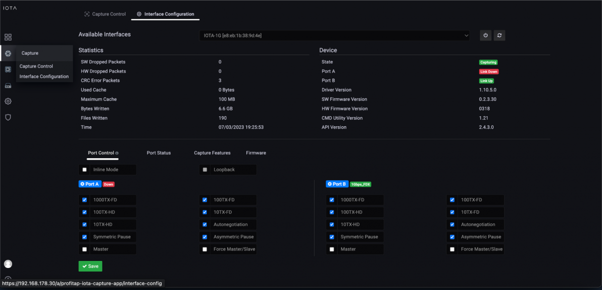
Figure 1: Configuration of the physical interfaces. In this case, 10/100/1000 Mbit/s Auto-Negotiation in SPAN Mode.
Placement of the IOTA
In the previously mentioned error pattern, the IOTA should be positioned near the client on which the error occurs; for example, by integrating it on a SPAN port of the access switch. In-line deployment between the client and switch is also possible if the client can be temporarily disconnected from the network to implement the IOTA for recording and analysis.
The IOTA should also be positioned at the transition between WAN and the perimeter firewall for verification. This allows us to verify whether the connection setup was dropped by the security component either in the WAN or on the target server.
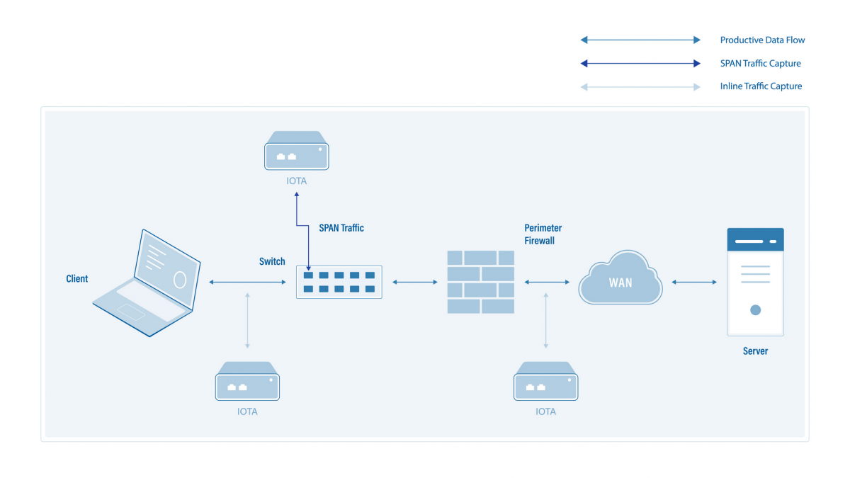
Figure 2: Placement of IOTA for packet averaging and analysis of the erroneous establishment of communication relationships with servers on the public Internet.
Start the capture
After we have prepared the physical interface and positioned the IOTA, we connect to the appropriate cable and start the capture process on the “Capture Control” page by clicking the “Start Capture” button at the bottom of the page. Alternatively, we can start the capture process by pressing the physical “Start Capture” button on the IOTA device. This speeds up the process and can be done by untrained or non-privileged persons.
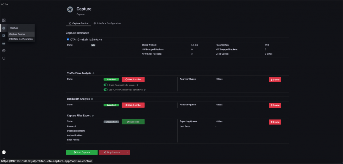
Figure 3: Start the capture using the “Start Capture” button on the “Capture Control” page.
Restricting the time range
As the first step of troubleshooting a faulty communication relationship, we must select the desired time range. We select either an absolute time range (From/To), or one relative to the current time, using the drop-down in the upper right area of the screen. This time range should be restricted as far as possible to simplify the following analysis.
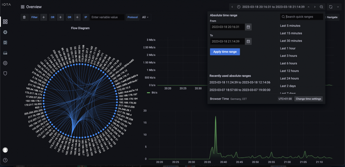
Figure 4: Overview Dashboard with a selection of absolute or relative time windows for analysis.
Searching for the root cause
When searching for error causes, we start with the host where the error occurred and then work our way to the root. However, not all error patterns can be analyzed with the same workflow. The only information we had, in this case, was that the affected host had the IP address 192.168.3.102 and that the error occurred on 03/18/2023 between 16:00 and 17:30. We did not know the IP address or port of the target server. By restricting the absolute time window, we can already see a significant reduction in communication relationships in the flow diagram of the Overview dashboard.
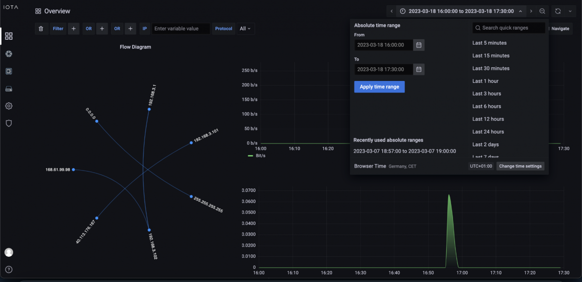
Figure 5: Restricting the absolute time range of the analysis to 03/18/2023 from 16:00 to 17:30.
We now have two options. The easiest one is to switch to the TCP Analysis dashboard. From there, we can filter by client source IP address and filter by TCP analysis flags. We can filter by ‘Incomplete 3-way’ and ‘Timed out’ connections to get failed connection attempts.
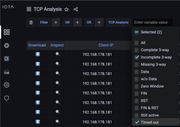
Figure 6: Set TCP analysis filters to incomplete handshakes and timed out connections.
Since we also filtered for the known source IP address, this easily gets us a list of failed TCP socket setups for this address. As we can see in Figure 7, there was one failed attempt to connect to the destination IP address 168.61.99.98 on TCP-Port 9043, which had an incomplete 3-way handshake and timed out.

Figure 7: Filter on TCP analysis flags on the TCP Analysis dashboard.
Thus, the initial SYN on the outbound transport path or the SYN/ACK on the return path seems to be blocked.
In the subsequent analysis, we checked the same communication relationship while simultaneously recording at the IOTA in-line between the perimeter firewall and the WAN, and recognized that the TCP SYN was still visible internally, but not externally. Therefore, the root cause of this error was a missing firewall rule.
Thus, we can see that failed TCP sockets are recognizable by Incomplete Handshakes, which are easily identifiable in the TCP Analysis dashboard of the IOTA. We also learned that we can use IOTA to check for missing or misconfigured firewall rules or bugs if we record and analyze at two points in our network.
IOTA benefits
The IOTA can significantly simplify and speed up troubleshooting to find the root cause. The dashboards provide easy-to-use filtering options. A simple click on a plus or minus sign next to, for example, the respective IP address or port, can be used to filter all communications related to this IP.
The absolute and relative time filters provide a quick filtering option for “looking for the needle in a haystack”. The flow details provide graphically well-prepared clues for the root cause analysis with information about the initial round trip time and the flow duration, including unidirectional bandwidth information and transferred data volumes.
Learn more about the IOTA solution at profitap.com/iota