IOTA 10G+ interfaces and LED behavior
Interfaces
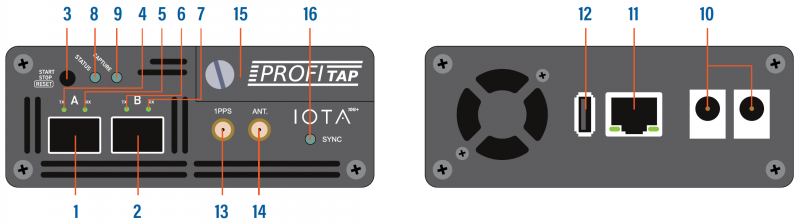
| 1, 2 | SFP+ port A and B |
|---|---|
| 3 | START/STOP/RESET button |
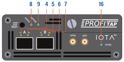
| 4, 5, 6, 7 | SFP and network status and activity LEDs |
| 8 | Status LED |
| 9 | Capture LED |
| 10 | 12 VDC power input (12V model) |
| 10 | 24-48 VDC power input (24V model) |
| 11 | RJ45 Management port (PoE+) |
| 12 | USB 3.0 port type A |
| 13 | SMA female connector (PPS in/out) |
| 14 | SMA female connector (GPS/GLONASS antenna) |
| 15 | Removable SSD |
| 16 | Sync LED |
LED behavior
| LED state | Meaning |
|---|---|
| 4+5 and/or 6+7 orange | No SFP module present or detected. |
| 4+5 and/or 6+7 green slow blink | No link. |
| 4+5 and/or 6+7 red | Connect additional power. |
| 5 and/or 7 green | SPAN mode, link up. |
| 5 and/or 7 green fast blink | SPAN mode, traffic activity. |
| 4+5+6+7 green | In-Line mode, link up. |
| 4+5+6+7 green fast blink | In-Line mode, traffic activity. |
| 8 blinking orange 9 off | Booting |
| 8 green 9 green | Running |
| 8 green 9 blinking green | Capturing |
| 8 blinking orange and green 9 blinking orange and green | Updating |
| 8 blinking red 9 blinking red | Hardware failure |
| 8 blinking orange 9 blinking orange | Factory reset |
| 8 blinking green 9 off | Shutting down |
| 8 off 9 off | Shutdown completed |
| 16 on | Internal timestamp synchronized with the configured time system (GPS, NTP, etc.) with an accuracy of ± 16 ns. |