Table of Contents
Theory of operation
Traffic management on the XX-Series rev. 2 is done using rules and rule sets.
Rule sets are traffic management profiles created by the user. Multiple rule sets can be created, with one of them active at any given time.
A rule set consists of the following facilities:
- Traffic rules
- Load balancing groups
- Ingress rules
Rules define how the traffic will be processed by the packet broker. Only data matching at least one of the defined rules will pass through, everything else will be dropped.
XX-Series rev. 2 devices support up to 511 “one port to one port” rules, or “interface links”. Each rule can contain one or more interface links. For optimizing rule utilization, see Optimizing rule consumption.
Load balancing groups are logic groups of ports that are used to distribute the traffic stream across multiple interfaces.
Ingress rules are used to manipulate traffic on the interface ingress pipeline.
Rules and rule sets are configured on the web GUI's Traffic Management page.
The Active tab displays the currently active rule set and its details, including the filtered interfaces, interfaces linked in load balancing groups, and ingress rules.
The Rule Sets tab displays the list of existing rule sets on the device. The active rule set is highlighted. Users with appropriate permissions can create, configure, activate, rename, delete, import, and export rule sets.
After clicking the configure button of a rule set, rules can be added, modified, or deleted.
After configuring a rule set, it can be activated right away, or kept inactive for future use.
Rule set configuration
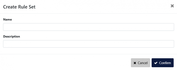
To create a new rule set, navigate to the Traffic Management > Rule Sets page, click the Create Rule Set button, enter a name, a description (optional), then confirm.

Several actions are available for each rule set:

 Clone the rule set
 Configure the rule set
 Apply the rule set (i.e. set it as active, which will replace the current active rule set)
 Edit the rule set's name and description
 Delete the rule set
To configure a rule set, click the configure button for that rule set on the Traffic Management > Rule Sets page. You can also configure the currently active rule set directly from the Traffic Management > Active page.

- Diagram/Table: The main view can be toggled between Diagram and Table view.
- Resource usage: Displays a count of the hardware resources used by the configured rules.
- Configure: Opens a menu allowing you to modify the rule set's name and description.
- Apply: Sets this rule set as active (replaces the current active rule set).
- Back: Navigates back to the list of rule sets.
Rule Set Configuration menu
The Rule Set Configuration menu, accessible by clicking the Configure button in the top-right corner of the screen, allows you to modify the rule set's name and description.
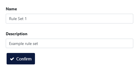
Diagram view
The Diagram view allows you to create and manage traffic rules visually and provides a clear, intuitive overview of them.
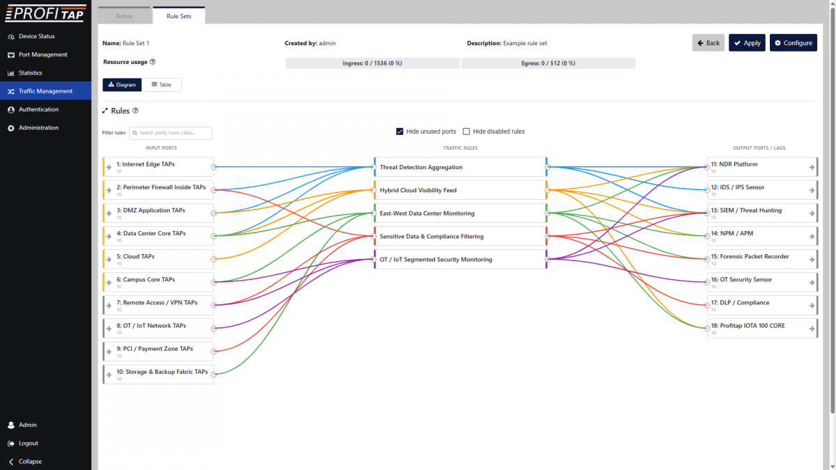
Example of a rule set with traffic rules in the Diagram view.
A new, empty rule set will be displayed as shown below, with input ports on the left side and output ports and load balancing groups on the right side. Make sure the Hide unused ports option is disabled.
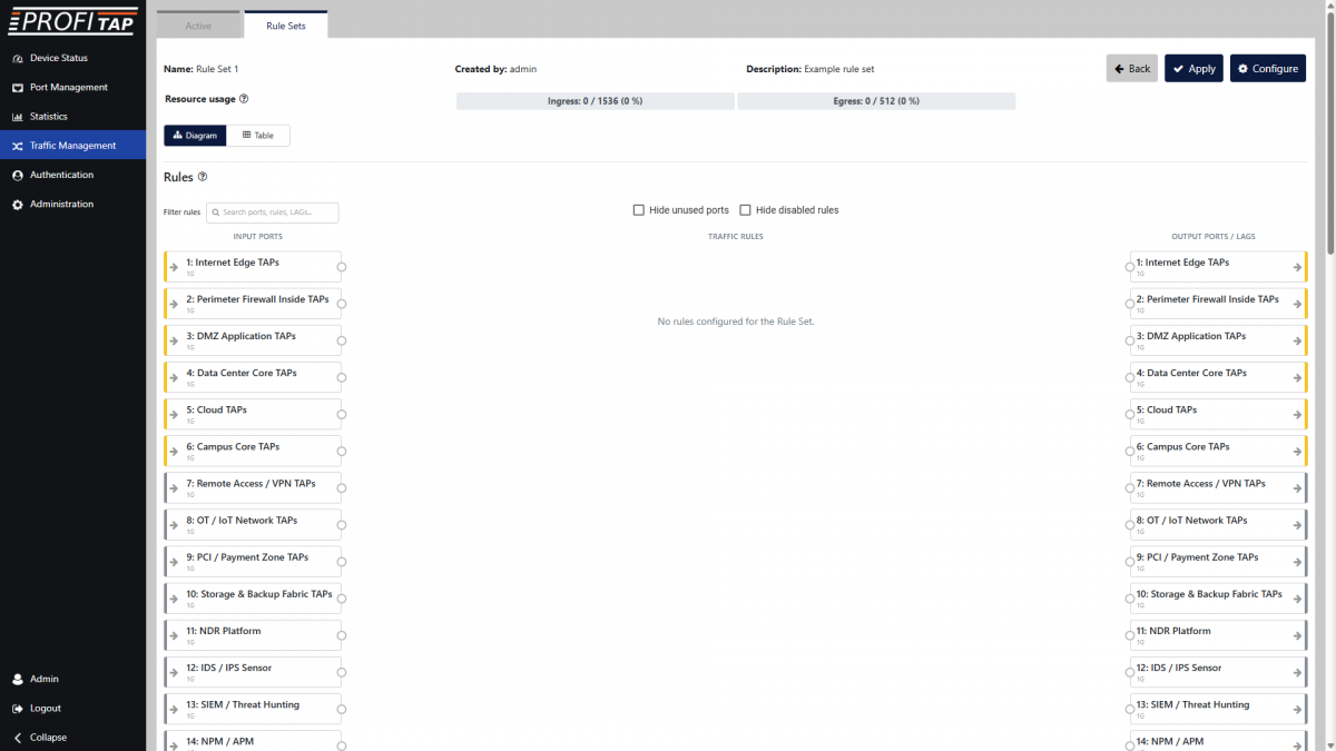
Empty rule set in the Diagram view.
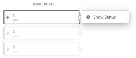
Clicking a port from the INPUT PORTS list, then Show Status, or simply double-clicking the port, will open its Status window.
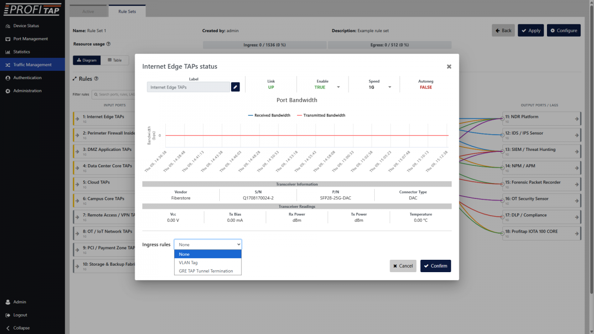
In this Status window, you can change the port label, speed, enable/disable the port, and set an ingress rule if desired.
Note that creating an ingress rule is only possible if the Status window was opened from the INPUT PORTS list.
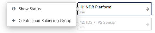
Clicking a port from the OUTPUT PORTS list gives the option to open its Status window or to create a load balancing group.
If one or more load balancing groups already exist, an additional option is available for adding the selected port to an existing load balancing group.
Double-clicking the port will open its Status window, where you can change the port label, speed, and enable/disable the port.
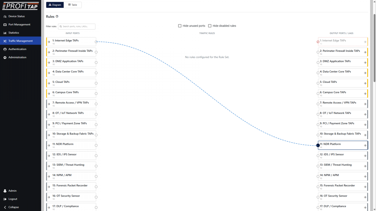
To start creating a new traffic rule, click and hold the circle on the side of an input port, and drag it to an output port or load balancing group. The Create Rule window will open, with the input port and output port or load balancing group selected.
For more details, see Creating a rule.
With multiple rules created, the Hide unused ports option helps provide a cleaner overview of the rule set.
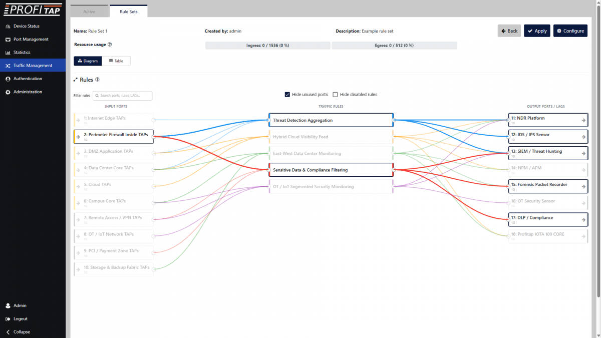
You can mouse over input ports, traffic rules, and output ports/load balancing groups to highlight relevant links.
You can click and drag the circle on the side of an input port, traffic rule, or output port/load balancing group to add connections to traffic rules.
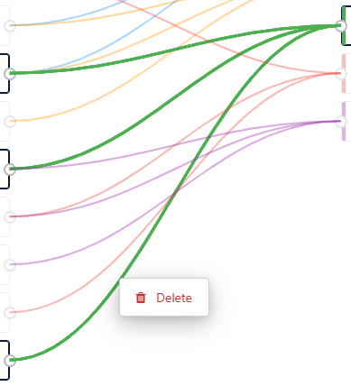
You can click specific connections and click Delete to remove it from a rule.
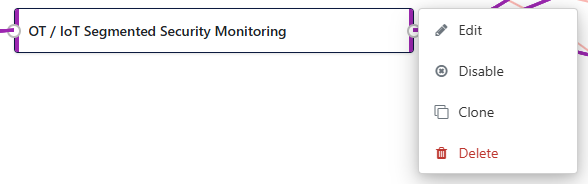
Clicking a rule gives you the option to edit it, disable/enable it, clone it, or delete it.
Disabled rules will be grayed out. Enabling Hide disabled rules will hide them from the diagram.
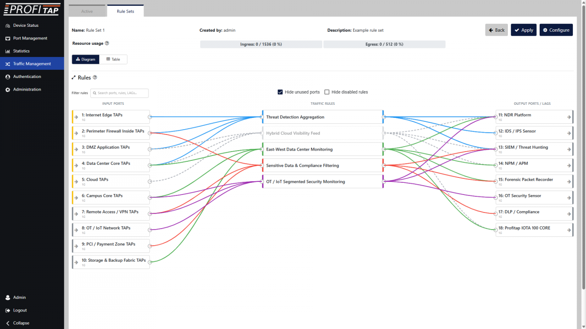
Table view
The Table view allows you to create and manage traffic rules in a table.
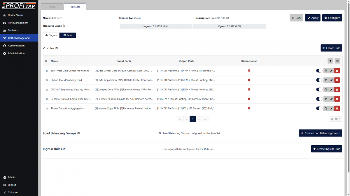
Each rule appears as a row in the table. The controls on the right side of each row allows you to enable or disable the rule, clone it, edit it, or delete it.
Click the Create Rule button to create a new rule (see Creating a rule).
Click the Create Load Balancing Group button to create a new load balancing group (see Load balancing groups).
Click the Create Ingress Rule button to create a new ingress rule (see Ingress rules).
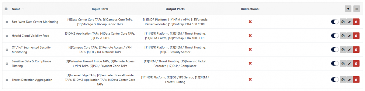
The +/- toggle on the left side of each row allows you to expand or collapse to contents of the rule. The same toggle in the header row expands or collapses all rows.
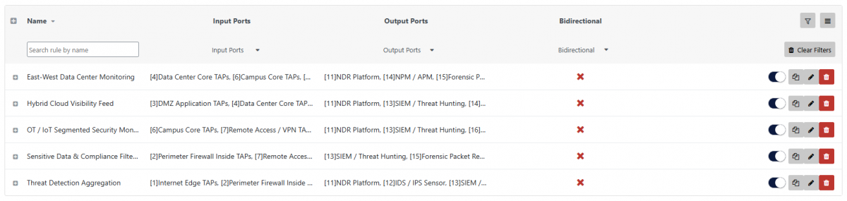
The Filter button on the right side of the header row opens controls for filtering the rules displayed in the table.
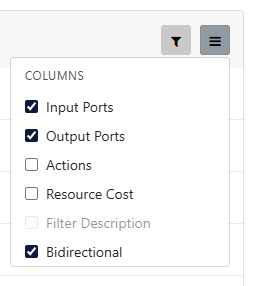
The Configure columns button next to the Filter button allows you to choose which columns to display or hide in the table.
Load balancing groups
Load balancing groups can be created in a rule set's Diagram view by clicking an output port and selecting Create Load Balancing Group, or in the Table view by clicking the Create Load Balancing Group button.
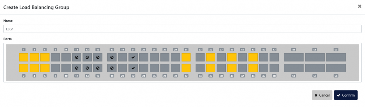
When a load balancing group is enabled for a group of interfaces, it is important to remember that when a port is inserted in one of these groups, it cannot be used in additional rules and will be displayed as unavailable in the port layout. This also means that ports that are already used as output in one or more rules cannot be added to a load balancing group. Additionally, in order to have a consistent behavior of the load balancing group, all of the interfaces belonging to that group must operate at the same speed.
The traffic is load balanced using the L3 and L4 fields to make sure to distribute the traffic flows consistently in the output ports.
Ingress rules
On the XX-Series rev. 2, users can define specific traffic manipulation rules to be performed on the interface ingress pipeline. Note that these operations will be performed before the filter and action engine described above. Users should ensure that the configured ingress rules don’t impact the functionality of the other rules.
Each Rule Set can include an independent set of ingress rules associated to each port. Note that it is only possible to have a single rule per port, and that these ports will only be available as input in other rules.
The available traffic manipulation options are:
- VLAN Tag: Adds a VLAN tag to all traffic incoming in the selected port;
- GRE Tunnel Termination: When enabled, users can associate a MAC and IPv4 Address to the selected interface. This will be available in the network and can be used to direct a GRE-TAP (Ethernet over GRE) tunnel in the NPB interface. The traffic will be decapsulated and processed further using the other user rules.
Ingress Rule - VLAN Tag
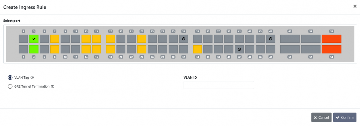
- VLAN ID: Set the ID with which to tag traffic.
Ingress Rule - GRE Tunnel Termination
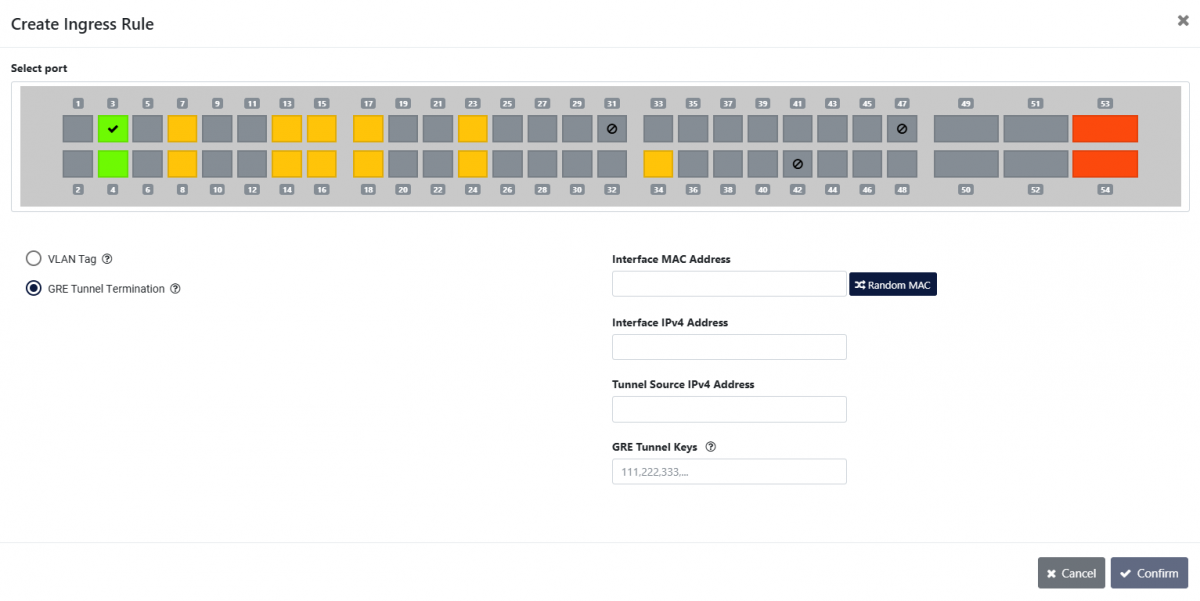
- Interface MAC Address: MAC address of the interface on the broker. The Random MAC button will generate one.
- Interface IPv4 Address: IPv4 address of the interface on the broker. This interface responds to ARP and ICMP packets destined to it.
- Tunnel Source IPv4 Address: IPv4 address of the sender.
- GRE Tunnel Keys: Multiple GRE Tunnel keys can be entered, separated by a comma.
Creating a rule
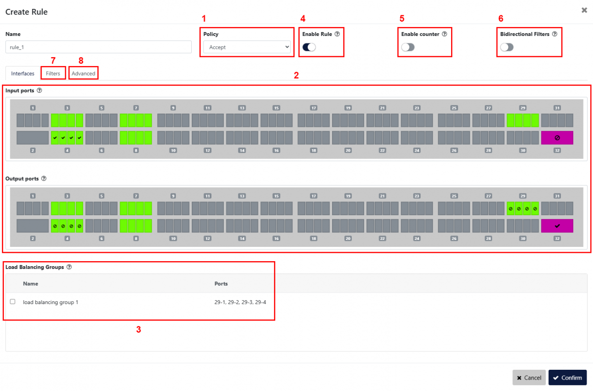
The first step in creating a new rule is defining the behavior of that rule [1]. The possible options are:
- Accept: Only traffic matching the defined filters will be forwarded;
- Drop: Traffic matching the defined filters will be removed from the stream.
The Input ports and Output ports sections [2] define which ports will be used as source for the traffic stream, and which ports will be used as destination.
⇒ When selecting multiple input ports, the traffic incoming on these interfaces will be aggregated (N:1 configuration).
⇒ When selecting multiple output ports, the traffic stream to these interfaces will be replicated (1:M configuration).
⇒ If multiple inputs and outputs are selected, the device will first aggregate the incoming traffic and then replicate the resulting stream to all of the selected output ports (N:M configuration).
If load balancing groups have been created, they appear in the Load Balancing Groups section [3]. Selecting one or more groups here will set them as output, in which case output interfaces won't need to be selected in the section above. Selecting multiple load balancing groups will replicate the traffic to each of these groups.
The Enable Rule toggle [4] can be used to enable or disable the rule.
The Enable counter option [5] can be enabled to start a counter monitoring the amount of packets matching the defined filter. These counters will be displayed in the Frame Match column of the Active tab's Rules table.
Enabling the Bidirectional Filters option [6] will make the rule match traffic in both directions by swapping source and destination fields (MAC, IP, and L4 port filters).
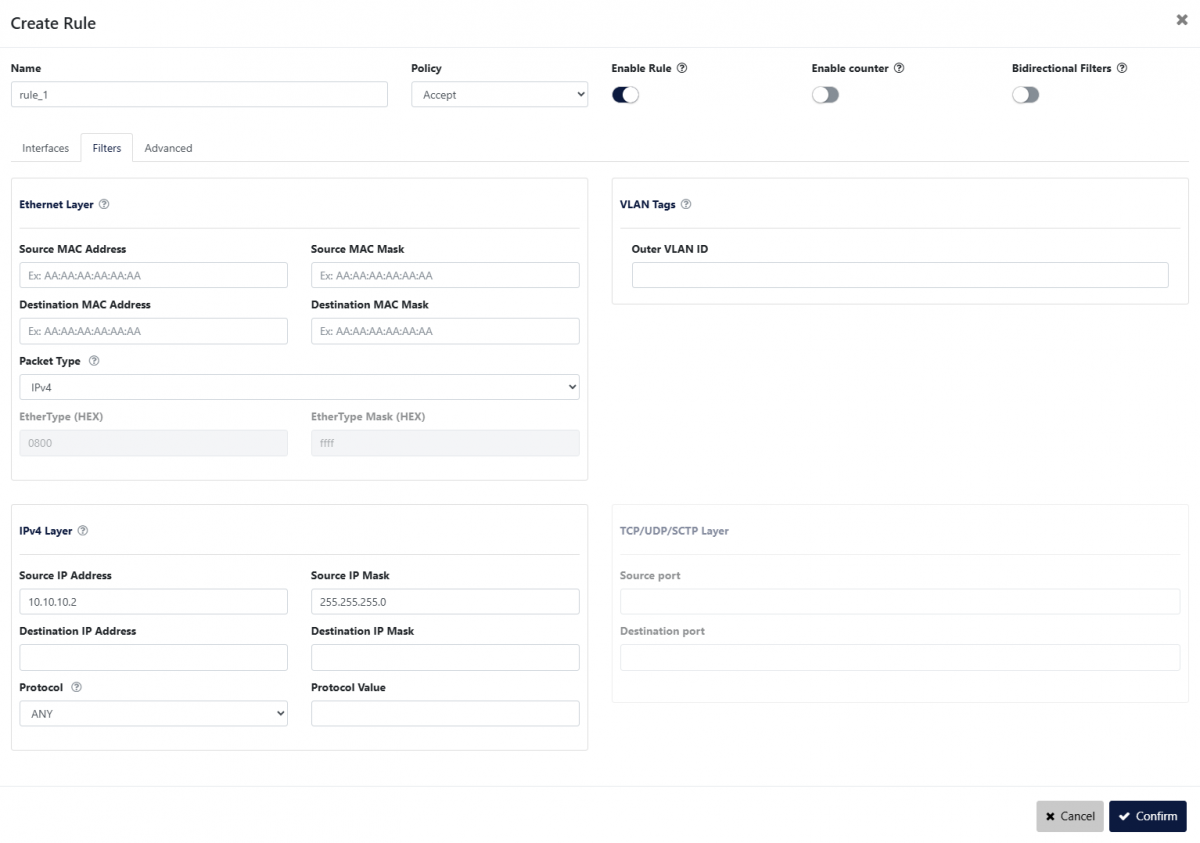
The Filters tab [7] allows the user to configure the way in which traffic is targeted, according to specific rules related to its L2, L3 and L4 packet headers:
- Ethernet Layer
Only frames matching MAC details configured in this section will be targeted (Source/Destination MAC Address, Source/Destination MAC Mask), with the possibility to select the packet type (IPv4, IPv6, ARP, TCP (IPv4/6), UDP (IPv4/6), SCTP (IPv4/6), Custom Protocol (IPv4/6), or any). - IPv4/IPv6 Layer
When IPv4/IPv6 is selected, the board will filter for any packet of those types. In order to filter for the IPv4/IPv6 details, the user needs to fill in the related fields (Source/Destination IP Address, Source/Destination IP Mask). The Protocol setting is only configurable for IPv4/IPv6, allowing the user to restrict the traffic to a specific type of L4 header (TCP, UDP, SCTP, ICMP, IGMP). Any allows filtering a custom EtherType or setting no filter for L3 headers. - TCP/UDP/SCTP Layer
When TCP/UDP/SCTP is selected in Packet Type or Protocol, only packets matching the transport layer details configured in this section will be filtered. - VLAN Tags
Can be used for filtering the first VLAN ID.
Note: If multiple filter fields are configured, only packets matching all filters will be targeted.
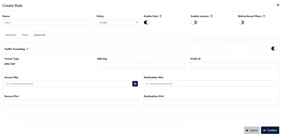
The Advanced tab [8] allows the configuration of GRE-TAP traffic tunneling, applied to the traffic in outbound.